
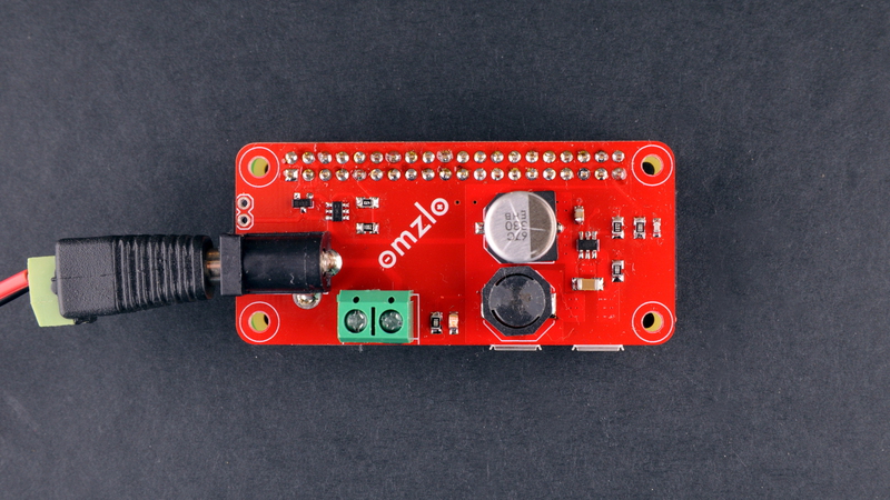
Our Omzlo PiMaster HAT has a DC power jack for a 12V to 24V input which is used for 3 purposes:
- Stepping input down to 5V to power the RaspberryPi
- Stepping input down to 5V/3.3V to power the PiMaster HAT itself (it hosts an STM32F0 ARM cortex microcontroller).
- Injecting power into our IoT CANbus network, to power our Arduino compatible nodes.
I thought it would be fun to take the 5V step-down converter of the Omzlo PiMaster HAT and make it into a standalone circuit that could be used to power a Raspberry Pi with a simple DC barrel power jack, which could accept any type of voltage between 7V and 28V.
This article explains how to build it.
From 24V to 5V
Why build this circuit when you can power a Raspberry-Pi with a 5V USB charger?
Well sometimes your project will use several voltages (e.g. 12V for a relay and 5V for the RPi): using a single power supply becomes a more elegant solution. Or perhaps you want to hook up your Pi to a big 12V battery. Or perhaps you just want to play with a DC switching regulator...
According to this website, a Raspberry-Pi 3 needs between 200mA and 800mA to function properly. To be on the safe side, we should aim for a solution that handles at least 1A. On the voltage side, we will aim for a solution that can handle inputs from 9V to 24V.
The simplest way to convert something like 12V to 5V is to use a linear regulator such as the venerable LM7805 or LM317. Unfortunately, converting 12V to 5V to provide a worst case 800mA with a linear regulator means that you will waste 5.6W of heat for nothing (i.e. (12V-5V)*0.8A ). In fact, you will waste more energy in the linear regulator than in the Raspberry Pi! Both the LM7805 and the LM317 would quickly fry! Things would be even worse if we wanted to start from 24V.
A switching regulator seems like a better alternative here. Many modern switching regulators achieve efficiencies above 80%. On the downside, switching regulators (buck converters) are more complicated to build.
One of the oldest "mainstream" switching regulator ICs that can handle our 9V to 24V range to input 5V is the MC34063. It's made by many manufacturers and is very versatile. While it's probably one of the cheapest switching regulators that exist out there, it requires some bulky external capacitors and a big inductor to work. It is also a bit "noisy" and less efficient because it's based on an old design.
Another popular choice is the LM2596: you will find many buck converters on eBay based on that chip or an imitation thereof. There's quite simple to use but not as cheap; at least the real ones.
As we were designing our Omzlo PiMaster HAT, we wanted to try a more modern alternative to these chips, hoping for high efficiency and low noise. Browsing around seeking inspiration I tried Texas Instrument's online power supply design tool: WEBENCH. After playing around with the tool, looking for a good compromise between BOM cost and PCB footprint, I opted for a design based on the TPS54202. This chip is branded as an "EMI Friendly Synchronous Step Down Converter". Sounds good!
Below is a schematic of the buck converter, following the guidance provided by WEBENCH:
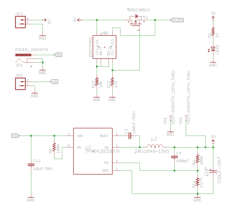
The input voltage (VIN) goes through the step-down converter (TPS54202), producing 5V. This voltage passes through a protection circuit (an "ideal diode" based on the DMG2305UX mosfet) and finally reached the Raspberry Pi (5V_RPI). The Raspberry Pi headers and mount holes are omitted on the schematic above, the full eagle design files are linked at the bottom of this page.
One interesting aspect of this switching regulator is the addition of "ideal diode" circuit, which is based on a recommendation made by the RaspberryPi Foundation. As explained here, this circuit blocks current from flowing from the Raspberry Pi to our power supply if the raspberry is already powered by another source (i.e. a USB cable). It acts like a diode with nearly 0V forward voltage, using a mosfet and a pair of matched transistors. For completeness, you could add a polyfuse to the circuit as well.
Building the circuit
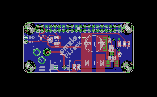
I decided to use the RaspberryPi Zero footprint for this board: it is compatible with the Raspberry Pi 2, Pi 3 and Pi Zero. As we learned the hard way, when designing a PCB for a switching regulator, it's important to follow as best as possible the layout recommendation provided by the manufacturer in the datasheet.
As you can see one the resulting bare PCBs below, I forgot to export part of the silkscreen to the GERBER files that were sent to the PCB manufacturer. "PiJack" is the cool name of the board but nobody will see it ;-)
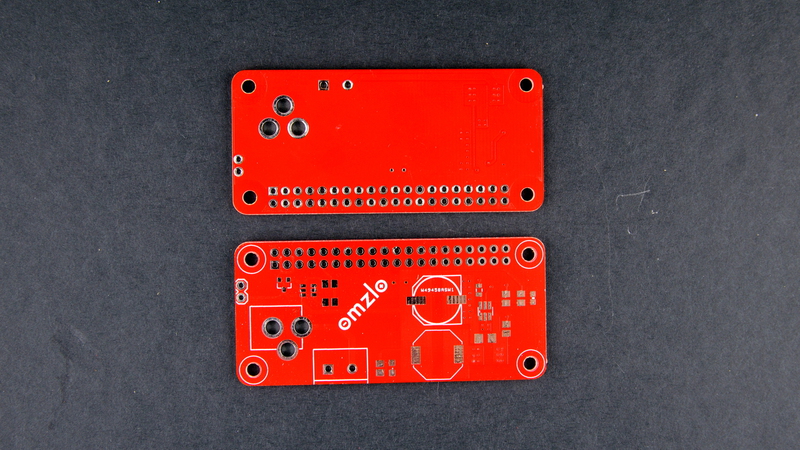
With the exception of one capacitor in size 0603, all passive components are in size 0805. As such, hand soldering the circuit with an iron presents no special difficulty, which the exception of the 15uH inductor. The small soldering pads tucked below the component make this a bit more challenging than the rest of the board (perhaps I just have no talent for this).
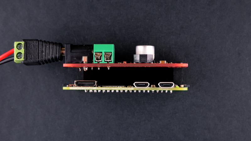
The picture below shows the final board alone, sitting on a Raspberry Pi Zero Wifi.
Testing the circuit
Switching regulators have a tendency to be more "noisy" than linear regulators. For digital circuits like the RaspberryPi, this does not matter much unless things get out of hand, but I was curious to see how bad/good things are.
A quick check on the oscilloscope shows a noise level of 20mv on the 5V output with a running Raspberry Pi zero. This measurement was not the most scientific one since I didn't take any precautions to reduce the influence of ambient noise sources but it shows that this circuit is fine.
Conclusion
Well, it works! I tested this power supply with inputs from 7V to 28V and on a Pi Zero, a Pi 2 and a Pi 3. The TPS54202 is rated for up to 2A so this should cover all needs.
You can find the EagleCAD files here.
If you liked this article, follow us on twitter or on our facebook page.
I will be at Maker Faire Rome 2017 on December 1-3. Come and say hello if you are there!
Comments
Thanks for providing this article... though I see the EagleCad files, I don't know how to open the files. I wish you could have left Build List of Electrical Components, and a source for your board. Better yet, you could SELL the Completed Boards... I'd pay double their cost!
Todd Naber, over 8 years agoWould be nice if this had some sort of low voltage circuit protection. I'm planning to use this on a solar powered pi setup... So it may shutdown if battery reserves drop too low.... But if it powers up as soon as the sun shines and it sees 12v from the solar charge controller before the battery has built up any charge, i could see it rapid cycling on-off-on-off and possibly corrupting the SD card.
John Tetreault, about 7 years agoLeave a comment