
A gardening project
The idea behind the Omzlo One project started a bit more than a year ago. I wanted to add some sensors in the garden outside the house, notably to:
- Get outside temperature and humidity,
- Automate the control of outside lighting with relays,
- Connect with the GPIO pin of a cheap IP camera I had installed,
- Detect when the dog was out of his compound, :-)
- And more...
Of course these sensors needed to be cheap enough that I could have a half a dozen to play with (and destroy).
As a start the cheapest approach seemed to go the WiFi way, with a battery powered solution based on the cheap ESP8266 chips out there. Unfortunately, there were a few problems. First, the outside WiFi signal turned to be quite weak or unreliable. Second, powering these devices with simple batteries in order to perform tasks such as activating relays, power mosfets, sending messages, meant that these batteries would need to be changed from time. I had a feeling I would likely end-up frequently outside unscrewing box covers in the rain…
Adding a WiFi repeater outside could solve the first problem, and adding some cables to bring power to the devices could solve the second one. In fact, doing some form of Power Over Ethernet (PoE) could allow me to forget about the WiFi issues altogether. But then, building an Ethernet micro-controller solution is not cheap (look at the price of Arduino Ethernet Shields), with real PoE being even more onerous… It also meant having an Ethernet switch and as many Ethernet cables as there would be devices out there. All this was clearly an overkill for such a micro-controller project.
Enter RS-485 and CAN-bus
The next idea was to use a simple serial communications over a common twisted pair and then adding another pair of wires to serve as ground and DC power lines. In order to cover distances than can reach over 30 meters (100 feet), two approach seem to dominate the horizon: RS-485 and CAN-bus.
With these approaches, all nodes share the same communication media: a common pair or wires. This is simple and simple is great! But as a consequence care must be taken to manage concurrent access to this media, and for this there are broadly speaking two types of configurations:
- A master-slave configuration. One node is designed as a “master” and initiates communications with other “slave nodes”, for example polling each “slave” node to ask if they have “something to say”. Nodes communicate according to a predefined order and are never in competition for the common media.
- A multi-master configuration. Any node can speak at any time, and some protocol is used to detect or avoid cases where two nodes “speak” simultaneously creating collisions on the common media.
I felt that the multi-master approach had some nice benefits: nodes could be plugged in the network at any time and then “broadcast” a message to all others to signal their new presence, enabling some form of auto configuration. Nodes could sleep, wake up and speak without waiting to be “detected” and “polled”…
In order to keep this post short, I will make a few simplifications here, and summarize my findings at that time as the following:
- RS-485 is essentially designed to work in “master-slave” mode. There are some approaches that implement “multi-master” over RS-485 by using collision detection: when a node detects that there is “garbage” on the line instead of the message it had sent, it assumes another node was “speaking” at the same time and resends the message later (using a random delay, typically exponential back-off). I had seen some suggestions that collision detection on RS-485 was somewhat unreliable when the number of nodes and traffic increases.
- CAN-bus is designed for multi-master mode. On a CAN bus pair of wires, if two nodes emit different bit values simultaneously -- one node sends a “1” and the other sends a “0” -- then only the “0” appears on the common media. CAN-Bus drivers use this property to detect that another node is speaking at the same time: the node that had sent the bit value “1” stops transmission immediately, and retries after the concurrent message ends. There are no collisions here: one node always has priority over the other.
Doing CAN-bus without CAN-bus.
Projects make mistakes and I made quite a few in designing the Omzlo One board.
One idea that turned out as a mistake was to create a hybrid between RS-485 and CAN bus: we would use the micro-controller’s USART to send data over a twisted pair, using a CAN bus transceiver instead of a RS-485 transceiver. We would emit and listen to the serial line simultaneously: when the data received was different from the data emitted, both nodes would interrupt their transmission and implement binary exponential back-off. In other words: CSMA/CD.
One of the first prototypes of this approach is shown in the picture below, with a homemade single sided PCB featuring an Atmega328p clocked at 8Mhz:

After a lot of trials and hours with the oscilloscope, it worked. But the final solution had many disadvantages:
- The node’s micro-controller is constantly “interrupted” to process serial characters even for packets that are not of any interest to the node.
- The node needs to implement some precise timing mechanism to measure packet gaps and back-off.
- CSMA/CD requires some form of random generator.
- Overall the supporting micro-controller code was rather large…
This was clearly not the best approach, but a good learning experience.
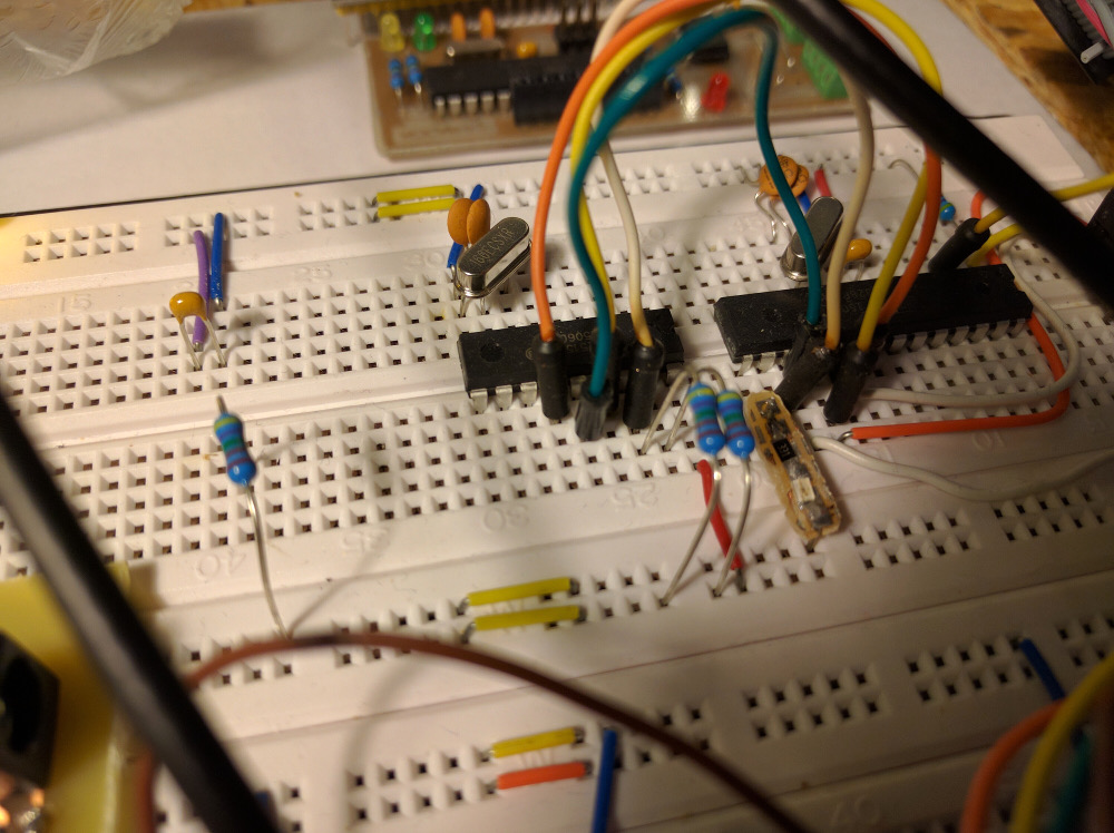
In the next iteration of our node design, I finally added a real CAN bus driver: the MCP 2515. I was back to the breadboard.
After some experience, I discovered that this approach was the big winner, allowing a true multi-master network and freeing the node’s micro-controller from unnecessary work. The details are hopefully worthy of another post.
Comments
No comment yet
Leave a comment