
- 1. Hardware
- 2. Software
1. Hardware
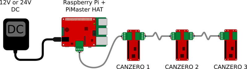
A NoCAN network is composed of a "master" and one or more "CANZERO" nodes. The master is built by combining a Raspberry Pi with the Omzlo PiMaster HAT.
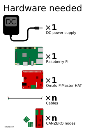
In this tutorial, we will assume that you have the following elements:
- A 12V DC power supply, preferably rated above 24 Watts (any supply between 6V and 24V should be OK).
- A working Raspberry Pi to which you are able to have command line access (e.g. through SSH).
- A PiMaster HAT.
- 4-wire cable or 8-wire UTP ethernet cable.
- Two CANZERO nodes.
This starting point provided here in this tutorial is easy to modify to add or remove CANZERO nodes.
1.1 Setting up the PiMaster
To set up the PiMaster, follow these steps:
- Solder the 40-pin GPIO header to the PiMaster HAT (if it is not already soldered).
- Unconnect the Raspberry Pi from any power supply and connect it to the PiMaster HAT with the 40 pin header.
- Plug the 12V DC power jack into the PiMaster HAT.
Note that the DC jack is "center positive": the central tip is positive (e.g. 12V) and the sleeve is ground.
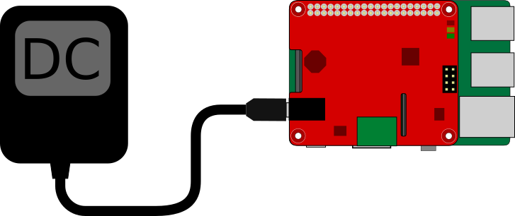
After completing these steps, the RaspberryPi should boot up, powered by the PiMaster HAT. Right when the power is switched on, the 3 LEDs in the upper left top corner of the PiMaster HAT will get animated briefly. The green LED, marked "A", should stay on.
To further test your setup, you will need to install nocand and nocanc as described later in this tutorial.
1.2 Adding CANZERO nodes
The first CANZERO node you add to your network will be connected to the PiMaster. The second node will be connected to the first CANZERO node, and so forth, forming a "chain."
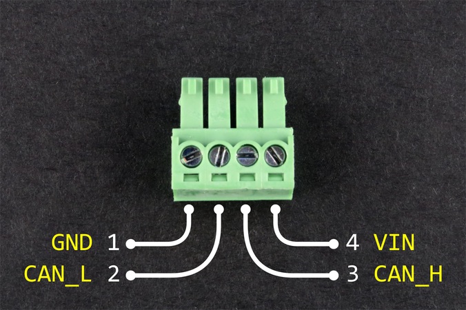
A NOCAN network uses four wires:
- GND: Ground
- VIN: DC power (12v or 24v)
- CAN_L: CAN bus low signal
- CAN_H: CAN bus high signal
1.2.1 Soldering the headers
If your CANZERO comes with pre-soldered headers, you may skip the following paragraphs.
If you need to solder a pair of 14-pin "Arduino-MKR style" headers to your CANZERO, you can use the procedure below.
The trick is to use a pair of additional break-apart male headers to create a stable rectangular jig to solder the CANZERO on top, as shown below.
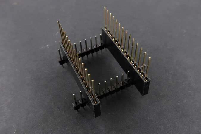
To do this, first, place the two 14 pin headers through the CANZERO board. Then place a pair of break-apart male headers across the 14 pin headers as shown below.
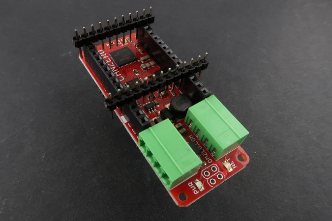
Next, flip around the board and start soldering. It's best to solder first the 4 corners (5V, AREF, Pin 5 and Pin 6) and then the rest of the pins. Note that the pin marked GND will take a little more time to solder because it takes longer to heat up.
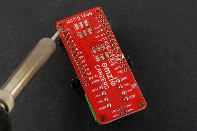
After soldering, remove the break-apart male headers and you are done.
1.2.2 Making cables
The first step is to create cables using the 3.5mm 4-pin pluggable headers that come with the CANZERO. For short distances (a few meters), any cable with four wires will do. For longer distances, cables with twisted pairs provide better robustness. A simple solution is to use Ethernet cable (UTP Cat 5): they can be found for cheap almost anywhere.
The picture below shows pinout used for the 3.5mm pluggable headers.
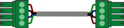
To make cables, connect pin 1 of the first 3.5mm plug to pin 1 of the second 3.5mm, then do the same for pin 2, pin 3, and pin 4. You should obtain a result similar to the illustration below:
If you don't have a four-wire cable available in your toolbox, consider using an Ethernet cable: they are ubiquitous and relatively cheap. Ethernet cables are formed with eight wires, assembled as four twisted pairs. Though you only need four wires for NoCAN, you will get better performance if you use all 8 wires by reducing power losses due to copper resistance over long distances:
- use three wires for ground,
- use three wires for VIN (e.g. 12V or 24V).
- use one twisted pair with one wire for CAN low (CAN_L) and one wire for CAN high (CAN_H)
We strongly suggest using the following wiring convention when using Ethernet cables. This will facilitate debugging and interoperability with other NoCAN networks:
| NoCAN 3.5mm pin | Ethernet wire color codes |
|---|---|
| 1 (GND) | Orange, Orange/White, Green/White |
| 2 (CAN_L) | Blue |
| 3 (CAN_H) | Blue/White |
| 4 (VIN) | Brown, Brown/White, Green |
The picture below shows two wiring examples: on the left, a simple set of 4 wires, and on the right an Ethernet cable wired according to the convention described above.
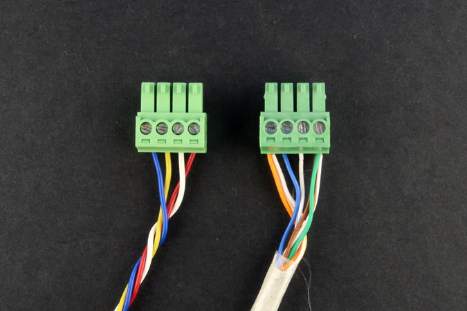
WARNING: it's easy to misconnect these 3.5mm plugs by accidentally fitting wires below the slot where they are supposed to be inserted. Always visually inspect the connections carefully.
1.2.3 Connecting to the PiMaster
Once your cables are ready, you can use them to connect your CANZERO nodes to the PiMaster, as illustrated below.
For large networks that run over 100 meters (330 feet) or with many nodes, it may be necessary to add a termination resistor on the last CANZERO node in the network. For this purpose, get a 120-ohm leaded resistor and screw it into pins 2 and 3 of a 3.5mm 4-pin pluggable header. Next, plug this "terminator" in the last CANZERO node in your network.
The network will not be powered and active until you launch nocand as detailed in the next section.
2. Software
2.1 Installing nocand
nocand is the server that manages a NoCAN network. It assigns node IDs to each node in the network and keeps track of open channels used to communicate through the network. It also acts as a gateway between the network and the outside world.
nocand needs SPI to be enabled on the Raspberry Pi and the wiringpi library to be installed.
To check if you have already installed wiringpi, simply type gpio -v in a shell terminal on your Raspberry Pi that is connected to the PiMaster HAT.
If you get something you are all set.
Otherwise, you will need to install wiringpi.
On recent versions of Raspbian, you simply need to type:
sudo apt-get install wiringpi
If that doesn't work on your system, you can install the latest version of wiringpi directly by following the instructions provided at http://wiringpi.com/download-and-install/ .
Next, to enable SPI, launch the raspi-conf utility by typing:
sudo raspi-config
In the menu select Interfacing Options, then SPI and finally answer yes to the question Would you like the SPI interface to be enabled?.
Note that not all versions of raspi-config have the same layout, so you might need to search for the SPI option in a different sub-menu (e.g. older versions of raspi-config have SPI in the Advanced Options menu).
You are now ready to install nocand.
To do this, open a shell terminal on the Pi and first download the nocand application. You can do this by typing:
wget -N http://omzlo.com/downloads/nocand-linux-arm.tar.gz
Untar the archive to extract the executable nocand by typing tar xvf nocand-linux-arm.tar.gz. Put nocand in a convenient directory, potentially adding that directory to your path (e.g. edit the PATH variable in ~/.profile).
Next, to make your life easier, you should create a configuration file called config in a subdirectory named .nocand of your home directory, using your favorite editor (e.g. mkdir ~/.nocand followed by nano ~/.nocand/config), and providing the following content:
auth-token = "yoursupersecretpassword"
The AuthToken value ("yoursupersecretpassword") will be used to authenticate connections from the nocanc tool to your nocand server. You should change the value provided in the example above to a secret password of your choice.
Testing your network with nocand
You are now ready to test your setup, by typing ./nocand server in the directory where you stored the nocand executable. If everything is OK, you should see the following output on the screen.
22018/04/25 19:05:14 INFO Connected to driver using SPI interface at 250000 bps
2018/04/25 19:05:14 INFO Reseting driver
2018/04/25 19:05:14 DEBUG+ (0) SPI SEND 3: 010200 (SPI_OP_RESET)
2018/04/25 19:05:14 DEBUG+ (0) SPI RECV 3: ffa000
2018/04/25 19:05:14 DEBUG+ Waiting for TX line to be HIGH
2018/04/25 19:05:17 DEBUG+ TX line is HIGH
2018/04/25 19:05:17 DEBUG+ (1) SPI SEND 19: 02000000000000000000000000000000000000 (SPI_OP_DEVICE_INFO)
2018/04/25 19:05:17 DEBUG+ (1) SPI RECV 19: 0043414e3000011d0010001743434334353520
2018/04/25 19:05:17 INFO Firmware version 0.1, signature='CAN0', chip id=1d0010001743434334353520
2018/04/25 19:05:17 INFO Driver signature verified
2018/04/25 19:05:17 DEBUG+ (2) SPI SEND 2: 0401 (SPI_OP_SET_POWER)
2018/04/25 19:05:17 DEBUG+ (2) SPI RECV 2: 00a0
2018/04/25 19:05:17 DEBUG+ (3) SPI SEND 11: 0300000000000000000000 (SPI_OP_POWER_LEVEL)
2018/04/25 19:05:17 INFO Listening for clients at [::]:4242
2018/04/25 19:05:17 DEBUG+ (3) SPI RECV 11: 8040003e050000f7050306
2018/04/25 19:05:17 DEBUG+ Driver voltage=11.9, current sense=0 (~ 0 mA), reference voltage=3.33, status(40)=+powered.
[...]
When nocand launches, it resets the PiMaster HAT and the 3 LEDs in the right top corner of the board with blink briefly a few times. The network will power up and both the Green and Orange LEDs labeled 'A' and 'B' will remain on. If the red LED switches on, you likely have a short circuit in your network, typically as the result of a cabling misconfiguration.
If the application blocks for more than a 10 seconds on the line "DEBUG+ Waiting for TX line to be HIGH" the PiMaster is likely in an undefined state: restarting the Raspberry Pi should fix this. If you get a message saying "panic: SPI driver signature check failed.", it likely means that the PiMaster HAT is damaged.
You can stop nocand at any time by pressing ctrl+C.
The last line in the logs above also gives some useful information:
2018/04/25 19:05:17 DEBUG+ Driver voltage=11.9, current sense=0 (~ 0 mA), reference voltage=3.33, status(40)=+powered.
Driver voltage indicates the detected DC voltage that powers the Raspberry Pi and your network. The status(40)=+powered shows that everything seems powered correctly without any electrical faults.
The next step is to check that the CANZERO nodes are connected correctly. If at least the first CANZERO node is connected correctly the logs will continue to display information similar to the lines below:
[...]
2018/04/25 19:05:19 DEBUG+ (4) SPI SEND 15: 090000000000000000000000000000 (SPI_OP_FETCH_DATA)
2018/04/25 19:05:19 DEBUG+ (4) SPI RECV 15: 180d9014010008080b06434d54031f
2018/04/25 19:05:19 DEBUG+ (5) SPI SEND 2: 0a00 (SPI_OP_RECV_ACK)
2018/04/25 19:05:19 DEBUG+ (5) SPI RECV 2: 0080
2018/04/25 19:05:19 DEBUG++ RECV FRAME EXT@90140100 8: 08 0b 06 43 4d 54 03 1f>
2018/04/25 19:05:19 DEBUG ** Received <nocan-sys-address-request node=0, func=1, param=0, len=8, data=080b06434d54031f> **
2018/04/25 19:05:19 INFO Device 08:0b:06:43:4d:54:03:1f has been regsitered as node N1
2018/04/25 19:05:19 DEBUG+ ** Sending <nocan-sys-address-configure node=0, func=2, param=1, len=8, data=080b06434d54031f> **
[...]
The line INFO Device 08:0b:06:43:4d:54:03:1f has been registered as node N1 indicates that a first CANZERO node has been correctly registered in the network. You should get a similar message for each node in the network (identified as N1, N2, N3, etc.).
You may see a WARNING saying that message of type nocan-sys-channel-subscribe ... was not processed. This warning can be safely ignored.
After a few seconds, you will also power status messages such as the following:
2018/04/25 19:12:17 DEBUG+ Driver voltage=11.9, current sense=7 (~ 10 mA), reference voltage=3.33, status(40)=+powered.
Here, the value of current sense gives a very rough estimate of the power consumption of the nodes in the network. When this value is 0, it means that the network is likely disconnected. This value will increase as you add nodes. If this value goes above a specific limit (approx. 4A by default), the PiMaster will cut off the power provided to the network as a safety measure.
Another way to check for potential connection issues is to visually inspect the green LEDs of the CANZERO nodes. During normal bootup, the green LED marked "NET" on the CANZERO will blink with regular frequency for 10 seconds and then stay fully on, once the node is registered with the PiMaster and fully booted. In case of an issue, this LED will blink twice rapidly and then stay off for a short while, before starting again to blink twice rapidly. This blinking pattern is typically the sign that the power connection to the board is correct but that the CAN bus is itself not correctly connected: it worth checking pins 2 and 3 on every cable for misconnections.
Once you have installed nocanc, as described in the next section, you will be able to check the correct configuration of the network more simply.
Once your setup is more stable, and you want to run nocand permanently, you can try to use the screen utility. This way you can connect and disconnect from your Pi, while nocand is running. Alternatively, you may want to put nocand into a systemd startup script so the server starts up automatically each time your raspberry pi boots up.
2.2 Installing nocanc
nocanc is the application that enables you to interact with your NoCAN network. For example, you can use nocanc to send a message to nodes or upload an Arduino sketch to a node. You are free to install nocanc on a different machine than the one that runs nocand. In fact, it often makes sense to do so, by running nocanc on the same machine that runs the Arduino IDE that is used to develop the sketches that will be uploaded to various nodes.
2.2.1 On Linux or Mac OS X
First, download the nocanc executable that corresponds to your platform:
- On Mac OS X, download nocanc-darwin-amd64.tar.gz
- On Linux/Amd64, download nocanc-linux-amd64.tar.gz
- On Linux/Arm (Raspberry Pi), download nocanc-linux-arm.tar.gz
Untar and uncompress the downloaded archive and extract the nocanc executable in a directory of your choice.
Optionally, for greater ease of use, you can add that directory to your PATH environment variable.
Next, to simplify your life, use your favorite text editor to create a simple configuration file named .nocanc.conf and place it in your home directory (e.g. nano ~\.nocanc.conf).
The content of this file should look as follows:
event-server = "192.168.2.112:4242"
auth-token = "yoursupersecretpassword"
You will need to replace 192.168.2.112:4242 with the actual address of your Raspberry Pi machine running nocand. Similarly, you will need to replace yoursupersecretpassword with the same password selected for nocand on the Raspberry Pi.
Assuming all is set up correctly, you can test the connection by typing the following command at the command prompt, in the directory where you extracted the nocanc tool:
./nocanc monitor
The tool should output messages similar to these:
EVENT   bus-power-status-update-event   #6  Driver voltage=11.9, current sense=6, reference voltage=3.33, status(40)=+powered.
EVENT   bus-power-status-update-event   #6  Driver voltage=11.9, current sense=7, reference voltage=3.33, status(40)=+powered.
If the connection fails, you will see Error: dial tcp :4242: getsockopt: connection refused. Please check your setup. If you see Error: Request failed, code 2 it probably means that the AuthToken value is incorrect.
2.2.2 On MS-Windows
First, download nocanc-windows-amd64.zip, and extract the executable nocanc.exe inside the zip file.
As a good starting point for experimenting, you can put it in your user directory: if your windows username is "Foobar," then your user directory will typically be "C:\Users\Foobar\".
This directory is also defined as the windows environment variable %userprofile%.
Next, to simplify your life, use your favorite text editor to create a simple configuration file named _nocanc.conf that will be placed in the user directory (e.g. Notepad.exe C:\Users\Foobar\_nocanc.conf or Notepad.exe %userprofile%\_nocanc.conf).
The content of this file should look as follows:
event-server = "192.168.2.112:4242"
auth-token = "yoursupersecretpassword"
You will need to replace 192.168.2.112:4242 with the actual address of the nocand server running on your Raspberry Pi. Similarly, you will need to replace yoursupersecretpassword with the same password selected for nocand on the Raspberry Pi.
Assuming all is set up correctly, you can test the connection by opening a Windows shell (search for "cmd.exe" in the windows launch menu) and typing the following command:
nocanc.exe monitor
The tool should output messages similar to these:
EVENT   bus-power-status-update-event   #6  Driver voltage=11.9, current sense=6, reference voltage=3.33, status(40)=+powered.
EVENT   bus-power-status-update-event   #6  Driver voltage=11.9, current sense=7, reference voltage=3.33, status(40)=+powered.
If the connection fails, you will see Error: dial tcp :4242: getsockopt: connection refused. Please check your setup. If you see Error: Request failed, code 2 it probably means that the AuthToken value is incorrect.
2.2.3 Using nocanc to test your network
The simplest way to check the status of your network is to use nocanc's web interface:
- Type the command
./nocanc webui. - Open a browser window and type
localhost:8080in the address bar.
You should get access to a web interface like the one below:
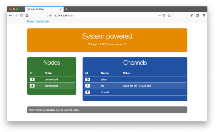
You will be able to see how many nodes are connected, what channels have been created.
2.2.4 Playing with nocanc
The web interface described in the previous paragraph should provide you with all that is needed to get started.
However, it's good to know that you can also get information directly from the command line with nocanc (so worries, if you don't like using the command line, you can skip this section).
The following examples assume that nocanc is running on Linux or MacOS. To translate the examples for Windows, simply replace all instances of ./nocanc with nocanc.exe
Typing ./nocanc list-nodes will provide a list of connected nodes in the network such as in the example below, which shows a two-node network.
$ ./nocanc list-nodes
# Nodes:
#1  08:0b:06:43:4d:54:03:1f connected
#2  07:01:06:43:4d:54:03:1f connected
By default, CANZERO nodes ship with a very simple default firmware that creates a channel named ledx where x is the node number. You can check this with the command ./nocanc list-channels, as in the example below:
$ ./nocanc list-channels
# Channels:
UPDATED #1  led1    ""
UPDATED #2  led2    ""
From this point on, you can switch the orange user LED on or off on any connected CANZERO node. For example by typing ./nocanc publish led1 1 you will switch on the orange user LED on node 1, while typing ./nocanc publish led1 0 will switch it off.
Of course, once you upload your sketches to a CANZERO node, this user LED "demo" will stop working. Creating your own Arduino sketches for the CANZERO is the topic of the final part of this tutorial.
To learn more about nocanc command line options, simply type nocanc help.
2.3 Configuring Arduino
For the most user-friendly experience, it is recommended to use Arduino version 1.8.9 or above.
To be able to use the Arduino IDE to create sketches for CANZERO nodes, you will need to install some additional components. This is a typical process needed to add non-native "Arduino-compatible" boards to the Arduino IDE. You can see for example the Sparkfun Tutorial describing how to install their SAMD21 board.
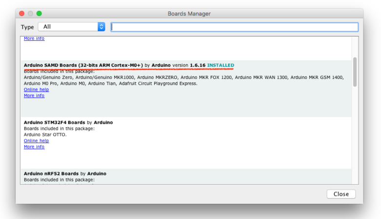
The first step is to add the native Arduino SAMD board definitions. This provides us with the necessary tools needed to compile Arduino sketches that target Atmel SAMD21 Arm Cortex M0+ boards, like the Omzlo CANZERO. To do this navigate to the board manager: Tools > Board > Board Manager. Then select Arduino SAMD Boards (32-bits ARM Cortex-M0+) by Arduino, and click on install.
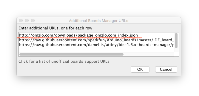
Next, navigate to Preferences and locate the Additional Boards Manager URLs field and click on the small icon on the right.
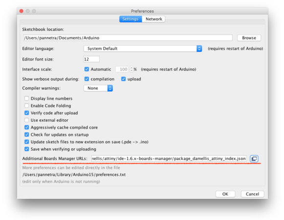
There you should add the following URL to the list, as shown below.
http://omzlo.com/downloads/package_omzlo.com_index.json
Finally, navigate back to the board manager: Tools > Board > Board Manager. Then select Omzlo SAMD boards and click install.
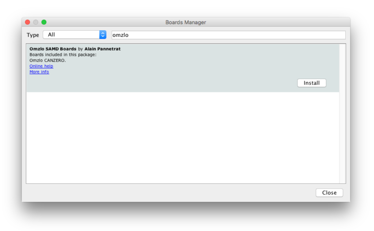
Note: If the Omzlo SAMD boards does not appear in the list the first time, please try again a few seconds later, to give the Arduino IDE enough time to download the board description.
2.4 Creating and uploading Arduino sketches
2.4.1 Starting with a very simple sketch
As a starting point, we will write the classic Arduino equivalent of "hello world": a blinking LED, using the builtin orange user LED. The corresponding sketch provided below four you to copy and paste:
void setup() {
  pinMode(LED_BUILTIN, OUTPUT);
}

void loop() {
  digitalWrite(LED_BUILTIN, HIGH);
  delay(100);
  digitalWrite(LED_BUILTIN, LOW);
  delay(100);
}
That sketch is very simple. In fact, it's so simple that it does not showcase any of the communication capabilities of the CANZERO. That's OK for now: it's just a test.
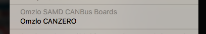
To prepare the sketch for compilation, navigate the Arduino IDE to Tools > Boards and select Omzlo CANZERO, as shown below.
The following steps will depend on your installation. Read on.
2.4.2 Uploading Arduino sketches the easy way
Let's assume that:
- You have Arduino version 1.8.9 or above
- On the same machine that runs Arduino, you have created a configuration file for
nocancas indicated previously
Congratulations! Uploading sketches will be super simple. Navigate the Arduino IDE to Tools > Port and select the node you want to upload to, as shown on the screenshot example below:
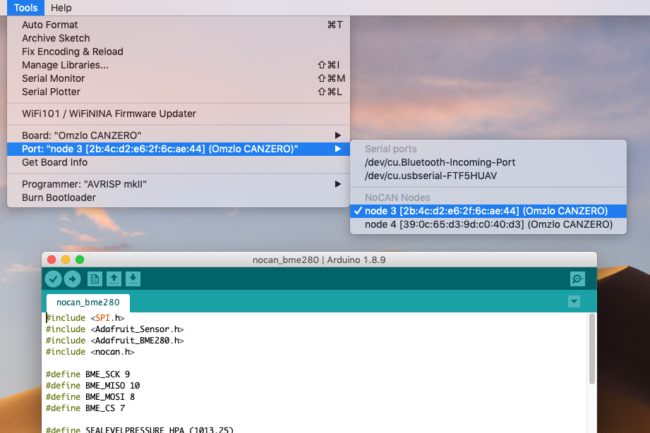
Then simply click on the "upload" icon, and you're done!
Once the upload has completed, after a few seconds the LED of the selected CANZERO node will blink rapidly.
2.4.3 Uploading Arduino sketches manually
If you have an older version of Arduino, will need to upload your sketches "manually".
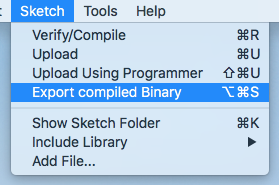
To do that, navigate to Sketch > Export compiled Binary. This will create a compiled version of your sketch, which is a file ending with the extension .hex.
Now you can use nocanc to upload your compiled sketch to the node of your choice. For example, if you want to upload the compiled binary canzero_hello_world.ino.omzlo_canzero.hex which is in the directory /Users/Omzlo/Arduino/canzero_hello_world, you would type the following command on a Mac OS X machine.
./nocanc upload /Users/Omzlo/Arduino/canzero_hello_world/canzero_hello_world.ino.omzlo_canzero.hex 1
On an MS-Windows machine, the command will look more like this:
nocanc.exe upload C:\Users\Omzlo\Documents\Arduino\canzero_hello_world\canzero_hello_world.ino.omzlo_canzero.hex 1
Once the upload has completed, after a few seconds the LED of the selected CANZERO node will blink rapidly.
What's next
You are now ready to explore the communication possibilities of the NoCAN network. As a start, you can look at the relay example provided in the introduction to the NoCAN platform as well as the examples provided in the NoCAN API description
Note: All logic on the CANZERO is 3.3V, like the Arduino MKR ZERO or the ESP8266 for example. Level shifting will be necessary to interface with legacy 5V circuits.