
Overview
The Omzlo CANZERO is an Arduino-compatible board with builtin CANbus networking and designed to be connected to a NoCAN network, enabling the creation of wired IoT applications.
The Omzlo CANZERO is designed to act as an independent node in a NoCAN wired network. Each CANZERO node can be programmed independently and communicate with other nodes in the network, creating applications with multiple sensors and actuators spread over a distance of 300 meters (1000 feet) and more.
At the heart of each CANZERO node is not one but two MCUs:
- A 48Mhz Atmel SAMD21G18A ARM Cortex M0+ with 256K flash, 32K ram, acting as the main processor.
- A 48Mhz STM32F042 ARM Cortex M0+, with 32K flash, 6K ram, acting as a CAN bus network driver.
Both MCUs communicate with each other through SPI as well as through two additional GPIOs.
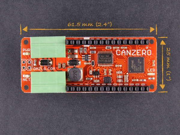
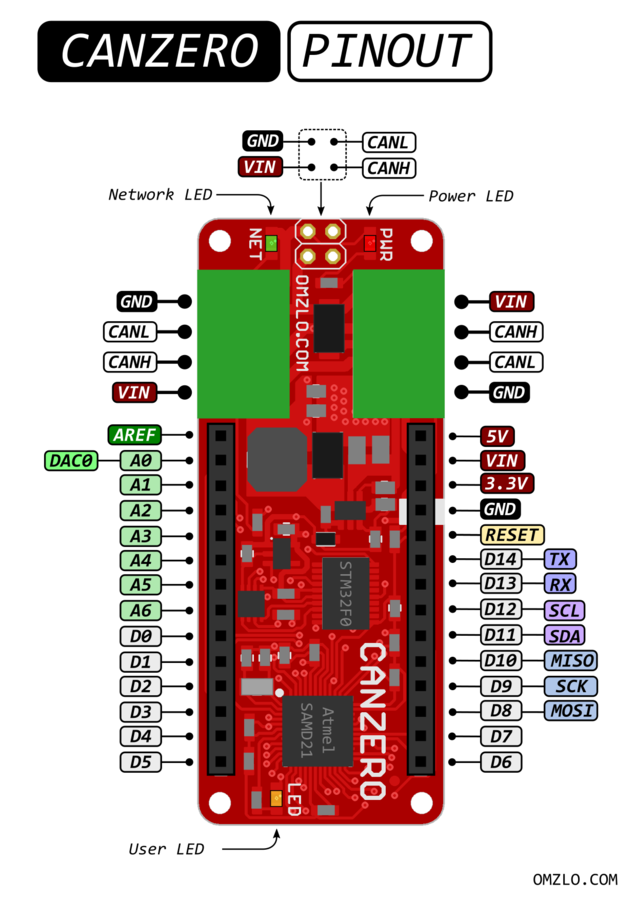
The Omzlo CANZERO shares the same mechanical footprint as the Arduino MKR Zero, measuring 61.5mm by 25mm (approx. 2.4" x 1"). As shown in the pinout diagram below, it also shares the same double row of 14-pin 2.54mm headers: most shields designed for the Arduino MKR Zero should work on the Omzlo CANZERO.
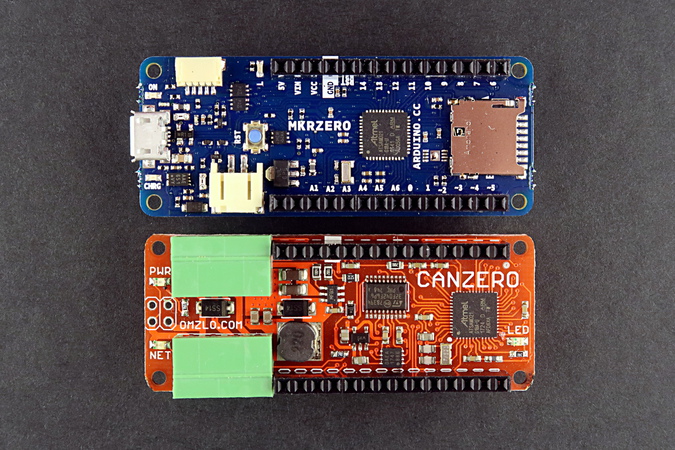
The CANZERO provides two four-pin 3.5mm pluggable headers designed to connect the board to the NoCAN network. However, contrary to the MKR Zero, the CANZERO does not offer an SD card slot, an I2S sound connector or a USB connector.
The main MCU is a SAMD21 which can also be found today on many other Arduino compatible boards. It runs compiled Arduino sketches created by the user. CANZERO "sketches" can be developed in the familiar Arduino IDE and the resulting applications can then be uploaded over the network to any selected node, thanks to a dedicated bootloader burned in the SAMD21 MCU.
The second MCU, an STM32F0, acts as a CAN bus driver, offloading the main MCU from tasks such as network packet buffering and re-assembly. It will also force the main MCU to reset and jump into the bootloader when it receives a specially formed packet. This allows you to recover from blocked applications or program errors, without physical access to the node or without initiating a power-down of the whole network.
Note: All logic on the CANZERO is 3.3V, like the Arduino MKR ZERO or the ESP8266 for example. Level shifting will be necessary to interface with legacy 5V circuits.
Pinout
Technical details
The CANZERO board integrates the following components:
- The main MCU: a SAMD21G18A.
- The network driver MCU: an STM32F042.
- A step-down switching regulator providing 5V (500ma max) from the 6V to 28V DC wired input (MCP16301).
- An LDO taking 5V down to 3.3V (300ma max) for the MCUs and board logic levels (MIC5401-3.3).
- A CAN bus transceiver IC (MCP2562).
- Three LEDs:
- Red: power status.
- Green: network or bootloader status.
- Yellow: user-defined (Arduino).
- Two 14-pin 2.54mm headers: provides digital, analog and power connections, following the same pinout as the Arduino MKR Zero.
- Two 4-pin pluggable 3.5mm headers provide connection to the network and power (VIN, GND, CAN_L, CAN_H).
- A reverse polarity protection diode and various passives.
The CANbus network runs by default at 125Kbps.
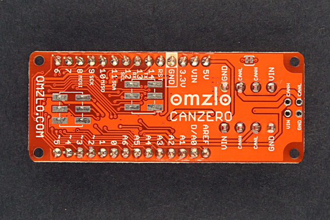
The bottom side of the board provides pin names and connection information.
Resources
- An introduction to the NoCAN platform
- Installing a NoCAN network: step-by-step instructions for hardware and software.
- A PDF version of the schematic is available here.
- Eagle CAD design files are available in our github repository.
- SAMD21G18 source code for the CANZERO main MCU.
- STM32F0 source code for the CANZERO CAN bus driver.
- Buy one from our online store.