
Overview
The NoCan IoT platform enables the creation of a simple wired network composed of Arduino-compatible nodes connected through CAN bus, targeting application domains where wireless approaches are not satisfactory.
It's a wired bus network: nodes are connected together forming a "daisy chain" with a single four-wire cable that brings both power and networking over distances of up to 300 meters (1000 feet). Power is provided as 12V or 24V DC and each node in the network steps it down to 5V and 3.3V. Networking is based on CAN bus running at 125kbps but is extended to offers advanced features such as publish-subscribe messaging and automated address assignement. Conceptually, our approach shares similarities with PoE (Power over Ethernet), but much is much simpler and cheaper to implement.
The network is composed of a set of nodes, managed by a single master. Each node is an Arduino-compatible board called CANZERO, which is based on the Atmel SAMD21 and offers the same pinout and size as the Arduino MKR Zero. You can write sketches in the Arduino IDE and then upload the resulting compiled binaries directly to any connected node over the network. Using the Arduino environment is not mandatory, however: the NoCAN libraries can also be used in a standalone SAMD21 project. The master is based on a Raspberry Pi combined with a specifically designed HAT: the Omzlo PiMaster. The master takes care of managing the network and acts as a gateway between the CAN bus network and the "outside world".
Nodes in the network can communicate with each other and with the outside world. A command-line application allows users to send and receive messages from nodes, enabling additional experimentation and automation through simple scripts. Alternatively, you can use a web interface to manage your network with a few clicks. The network can even optionally be controlled over the Internet with a smartphone, thanks to the blynk platform or by using a MQTT platform. All hardware, software, and specifications of the NoCAN platform are provided as open-source/open-hardware with the hope that they will be further improved by the community.
We call this platform "NoCAN" because it takes CAN-bus where it has never gone before!
Read on to learn more!
Hardware
Architecture
The NoCAN IoT platform is composed of:
- One Raspberry Pi associated with a PiMaster HAT.
- One or more CANZERO Arduino compatible nodes.
These elements are connected together forming a bus or "daisy chain" with a single cable providing both CAN-bus networking and DC power (typically 12V or 24V, but anything between 8V and 28V should work).
The following figure summarizes this architecture with a three-node network as an example.
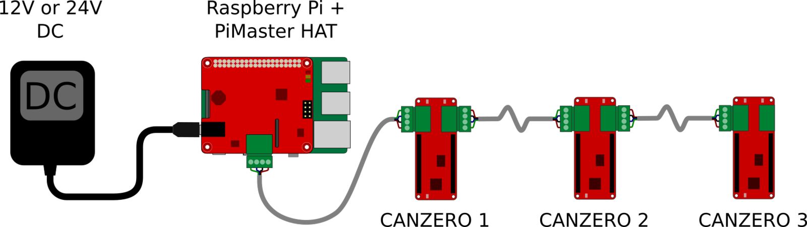
The Pi Master HAT only needs an 8 to 28V power supply, which is used to power both the network and the Raspberry Pi itself. The Raspberry Pi acts as a gateway between the outside world and the NoCAN network. This gateway can be controlled over WiFi or Ethernet, depending on the connectivity offered by the Raspberry Pi host.
The Omzlo CANZERO
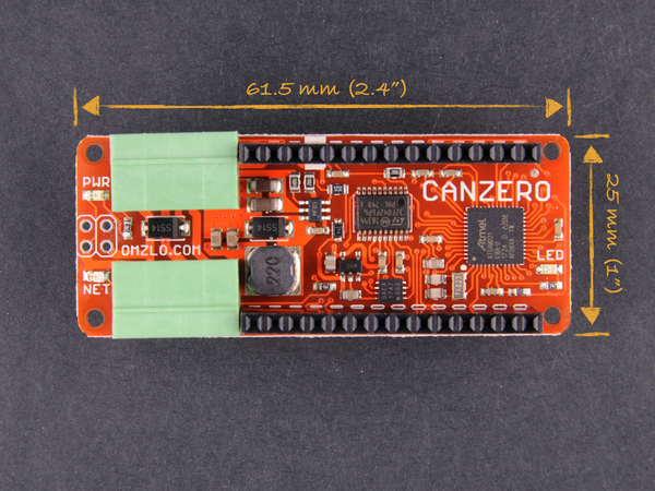
The Omzlo CANZERO is a dual-MCU board featuring:
- A 48Mhz Atmel SAMD21G18A ARM Cortex M0+ with 256K flash, 32K ram, acting as the main processor.
- A 48Mhz STM32F042 ARM Cortex M0+, with 32K flash, 6K ram, acting as a CAN bus network driver.
Both MCUs communicate with each other through SPI as well as through two additional GPIOs.
The Omzlo CANZERO shares the same mechanical footprint as the Arduino MKR Zero, measuring 61.5mm by 25mm (approx. 2.4" x 1"). It also shares the same 2x14 GPIO pin 2.54mm headers: most shield designed for the MKR Zero should work on the Omzlo CANZERO. The CANZERO provides two four-pin 3.5mm pluggable headers designed to connect the board to the bus network. However, contrary to the MKR Zero, the CANZERO does not offer an SD card slot, an I2S sound connector, or a USB connector.
Once compiled, Arduino sketches can be uploaded to the CANZERO over the network, thanks to a dedicated bootloader burned in the SAMD21 MCU.
The second MCU, an STM32F0, acts as a CAN bus driver, offloading the main MCU from tasks such as network packet buffering and re-assembly. It also resets the main MCU if requested: this can be super helpful if your firmware somehow gets "stuck."
More information on the CANZERO can be found on this dedicated page, including a pinout diagram.
The Omzlo PiMaster HAT
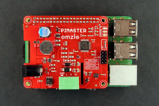
The Omzlo Pi Master is a HAT (Hardware Attached on Top) providing a gateway between the CAN bus network and a Raspberry Pi, which runs network managing software.
The Pi Master is built around an STM32F042 ARM Cortex M0+ running at 48Mhz. This MCU communicates with the Raspberry Pi through SPI and a few additional GPIOs. It performs three main functions:
- It acts as a gateway to the CAN bus network.
- It controls and monitors power delivered to the network (typically 12V or 24V).
- It powers the Raspberry Pi from a voltage source from 8V to 28V.
A software application called nocand running on the Raspberry Pi uses this gateway to manage the network by performing the following tasks:
- Powering up or down the network.
- Monitoring voltage and current levels.
- Registering CANZERO nodes, attributing to each one a unique address.
- Registering channels as part of the publish-subscribe protocol used in NoCAN.
- Resetting CANZERO nodes, activating their bootloader,
- Uploading or downloading firmware (hex files) to/from any CANZERO node.
As a built-in safety, a smart switch controlled by the MCU will automatically switch off the power distributed to the network if there is too much current drawn (typically above 3A). This could notably happen while fiddling with the cables that connect the CANZERO nodes together resulting in a short circuit.
More information on the Omzlo PiMaster HAT can be found on this dedicated page
Software
nocand: the NoCAN network manager
nocand (NoCAN daemon) is a software application written mainly in Go, which runs on the Raspberry Pi connected to the Pi Master HAT. Its primary role is to manage the CANZERO nodes on the network, assigning unique addresses to each node, and managing communication channels.
Once installed on the Pi, running the application is as simple as typing nocand server at the command prompt.
By default, the application will start by powering off the network, turning off the smart switch on the Pi Master HAT, and resetting its MCU. The MCU will then restart and power-on the network. All CANZERO nodes in the network will initiate a boot sequence and nocand will allocate a unique address to each one of them. The CANZERO nodes will also create and subscribe to channels, which will be allocated and managed by nocand.
The nocand application will also open a TCP server (by default on port 4242) to enable you to control and communicate with the NoCAN network, through another program called nocanc, described below.
For more details about nocand please see the manual page here.
nocanc: the NoCAN command line client
nocanc (NoCAN client) is a software application written in Go, which is used to interact with the NoCAN network running on the Raspberry Pi through a TCP server created by the nocand server. The nocanc application can run on a different host than the Raspberry Pi that is connected to the Pi Master HAT running nocand. It should run on Linux, OS X, MS Windows, or any other platform which can compile Go applications. Several nocanc clients can run concurrently.
The nocanc application can be used to:
- Publish a message to a channel, sending it to any node that has subscribed to that channel.
- Read the latest message that has been sent to a particular channel.
- List existing channels.
- List connected CANZERO nodes.
- Upload firmware to a CANZERO node.
- Download firmware from a CANZERO node.
- Monitor events in the network.
- Interface with a blynk server, enabling interactions with CANZERO nodes over the Internet using a simple smartphone.
- Interface with MQTT, translating messages between a NoCAN network and an MQTT broker.
The concept of "channels" used in NoCAN network simplifies the construction of distributed applications. You don't need to worry about the address of the node(s) you want to communicate with: simply send a message on a channel and all nodes that have subscribed to that channel will receive it. This approach is very similar to MQTT.
For example, if a CANZERO node in the network is connected to a relay and has created a channel called "relay", then closing the relay remotely could be as simple as typing the following command on the Raspberry-Pi:
nocanc publish "relay" "close"
Similarly, if a CANZERO node in the network has a temperature sensor and publishes temperature data on a channel called "temperature", then reading the temperature remotely could be as simple as typing the following command on the Raspberry-Pi:
nocanc read-channel "temperature"
If you are allergic to the command line, just launch our new web interface by typing:
nocanc webui
For more details about nocanc please see the manual page here.
Arduino compatibility
Programming CANZERO nodes in the Arduino IDE first requires the installation of a board description package following the instructions provided here. After that, it's a matter of including the <nocan.h> header in your sketch and calling the appropriate library functions.
Consider for example a CANZERO node connected to a relay through Arduino PIN 2. When PIN 2 is high, the relay closes and when PIN 2 is low, the relay opens. In the following sketch below, we create a channel called "relay" and subscribe to it. Then, each time the node receives a message starting with the letter 'c' (or the number '1') on that channel it will close the relay and each time it receives a message starting with 'o' (or the number '0'), it will open the relay.
// file name: sketch_nocan_relay.ino

#include <nocan.h>

void setup() {
  NocanChannelId cid;

  Nocan.open();
  Nocan.registerChannel("relay", &cid);
  Nocan.subscribeChannel(cid);
  pinMode(2, OUTPUT);
  digitalWrite(2, LOW);
}

void loop() {
  NocanMessage msg;

  Nocan.receiveMessage(&msg);

  if (msg.data[0]=='c' || msg.data[0]==1)
    digitalWrite(2, HIGH);
  if (msg.data[0]=='o' || msg.data[0]==0)
    digitalWrite(2, LOW);
}
Note that, for simplicity, the code above omits to checks function return codes for errors as you would expect in a more robust application.
There are three ways to upload firmware to a node in your NoCAN network.
First, you can configure your Arduino environment to enable sketch uploads directly from your Arduino IDE, as described here.
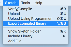
Second, the sketch can also be exported to a compiled binary (a hex file) from the corresponding Arduino IDE menu.
The compiled binary can then be uploaded to the desired CANZERO node in the network, identified by its address (a number between 1 and 127), using the nocanc program. For example, the following command will upload the compiled sketch binary called 'sketchnocanrelay.ino.omzlo_canzero.hex' to the CANZERO node number 1:
nocanc upload sketch_nocan_relay.ino.omzlo_canzero.hex 1
Finally, we have also developed a web interface that enables uploading firmware to nodes in an even more user-friendly manner, simply by 'drag-and-dropping' the firmware file on a webpage.
The command-line approach or the web interface can be used to upload sketches even if you don't use the Arduino environment.
Networking
Control your devices over the Internet with Blynk
Controlling your @Arduino project over #CANbus+Internet with a mobile app is now a thing. @blynkapp <a href="https://twitter.com/hashtag/IoT?src=hash&refsrc=twsrc%5Etfw">#IoT #NoCan pic.twitter.com/547H2nwJCI
— Omzlo Electronics (@OmzloElec) April 5, 2018
Blynk is a popular platform that enables controling devices such as Arduino boards over the Internet, through a simple mobile application. The NoCAN platform is designed to be optionaly connected to the Blynk platform, through nocanc command-line application. Blynk offers the concept of virtual pins, which can be mapped to 'channels' in the NoCAN platform.
Consider the previously described example of a CANZERO node connected to a relay, which is controlled through a channel simply called 'relay'. By issuing the following command, we will map the channel 'relay' to the blynk virtual pin '1':
nocanc blynk --blynk-token <auth_token> --writers 1::relay
Here <auth_token> will need to be replaced by you Blynk access token.
After that, if you define virtual pin 1 as a button in the blynk app on your mobile phone, then pressing the button will activate the relay over the Internet.
The above example showed only one mapping, but it's possible to define as many as needed. In order to avoid composing long command lines with nocanc while using blynk, it's possible to configure blynk through a configuration file and simply type:
nocanc blynk
You can also interface the NoCAN platform to an MQTT broker to connect NoCAN to IoT platforms such as Adafruit.IO or Cayenne.
For more information about connecting with blynk, please look at the corresponding subsection in the nocanc documentation.
Using MQTT
MQTT is very similar to the NoCAN network protocol that runs on CAN-bus. Both protocols use the concept of publish/subscribe. Whereas NoCAN publishes data to 'channels', MQTT uses the concept of 'topics' essentially the same way. MQTT is generally more featureful, offering choices in quality of service (QoS) that are not available with NoCAN. Because MQTT is a well-defined standard, there are many tools and online services that offer an MQTT service.
The NoCAN platform can also be interfaced with MQTT, and you can find further details here.
Building on CAN bus
The NoCAN IoT platform is based on CAN bus 2.0, a communication protocol originally created for the automobile industry and now used in other areas such as industrial systems. CAN is a wired bus that uses differential signals to communicate, much like RS485, offering automatic bus arbitration, prioritized messaging and robust error detection in ways not found in most other similar protocols.
These benefits come with some limitations, however, but the NoCAN platform uses several 'tricks' to overcome them. As a first limitation, CAN bus nodes are typically not designed to have dynamic addresses. In fact, node addresses are often assigned statically in firmware. NoCAN uses an address registration protocol to allow dynamic allocation of addresses to nodes. As a second limitation, CAN bus messages are limited to 8 bytes. Yet NoCAN messages can be up to 64 bytes long. The network driver MCUs (STM32F042) on each CANZERO node are capable of breaking down and assembling 8-byte CAN frames in order to process messages of up to 64 bytes.
Note: there is a newer version of CAN called "CAN FD" that offers some interesting improvements over CAN bus 2.0. However, it has not yet reached an adequate level of maturity and availability to be used as a foundation of the NoCAN platform.
For more information on the NoCAN protocol, please check out our draft NoCAN specification.
Resources
For tutorials, software, hardware, schematics, specifications and more, please check the links on our main project page.