
PIR (Passive infrared) sensors are simple yet effective devices that detect changes in of radiation in their field of view. Such changes are usually induced by a moving human or animal, so they are used for presence detection or alarm systems. We will discuss how to connect and use a PIR sensor in a NOCAN network and get notifications on a smartphone when the sensor is triggered, using blynk.
We will go through:
- The hardware architecture
- The Arduino sketch that runs on the CANZERO node connected to a PIR sensor.
- How to test our setup
- How to connect our PIR sensor to a smartphone
- Dealing with multiple PIR sensors
This article ends with a list of useful resources to find further information.
Hardware architecture
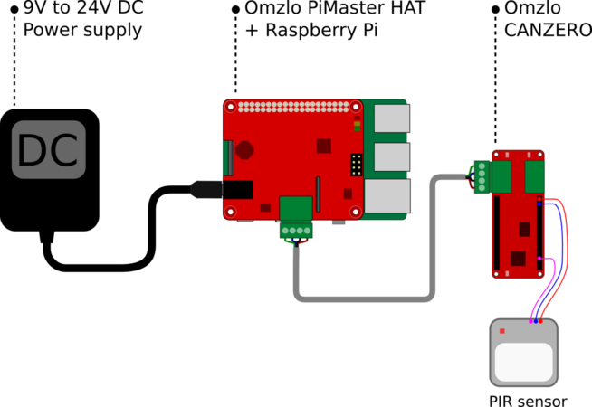
A bare minimum setup featuring a PIR sensor connected to a NOCAN network will look like the figure below, and will be composed of:
- A power supply (12V, 2A).
- An Omzlo PiMaster HAT and a Raspberry Pi.
- An Omzlo CANZERO Arduino-compatible node.
- A 12V PIR sensor.
PIR sensors can easily be found for your favorite Maker shop, eBay or Aliexpress. There are many tutorials and demos out there that use small 5V based PIR sensors, but our experience is that these 5V sensors are too fiddly and limited to be useful. On the other hand, for a couple of dollars or euros more, you can find 12V sensors that work very well. We picked one similar to this one found on eBay.
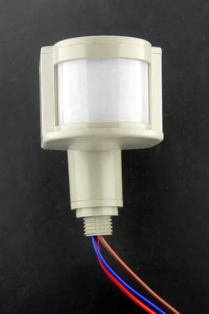
The sensor has three colored wires: Blue for GND, Brown for 12V and Red for signaling. Beware that these Chinese made PIR sensors don't always have a consistent color wiring, so doublecheck. The red signaling wire is normally at 0V (LOW) and jumps to 12V (HIGH) when the sensor is triggered. It stays at 12V for a specific time and then goes back down to 0V unless triggered again.
Connecting the power supply, Omzlo PiMaster, Raspberry Pi and CANZERO has already been covered in our extensive installation tutorial.
In the setup we described above, powering the PIR sensor is easy: since the NoCAN network is already powered by a 12V power source, we will use that same voltage to power the PIR sensor.
The CANZERO board has a VIN pin that provides whatever voltage is used to power the network, here 12V, so we will use that pin to power the PIR.
Similarly, the ground wire of the PIR sensor will be connected to the GND of the CANZERO.
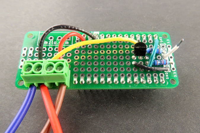
We now want to connect the signaling wire of the PIR to an I/O pin of the CANZERO. This connection requires a little bit of circuitry since the CANZERO I/O pins do not accept any voltage above 3.3V without risking damaging or destroying the board. The simple level shifter shown in the figure below will do the trick.
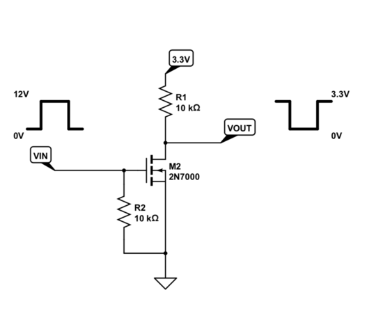
This level shifter, composed of one Mosfet and two resistors, is inverting: when the signal is high on the 12V side, it becomes low on the 3.3V side, and vice-versa.
We decided to use Arduino pin 6 on the CANZERO as our input pin.
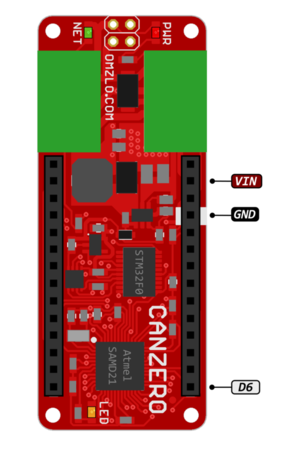
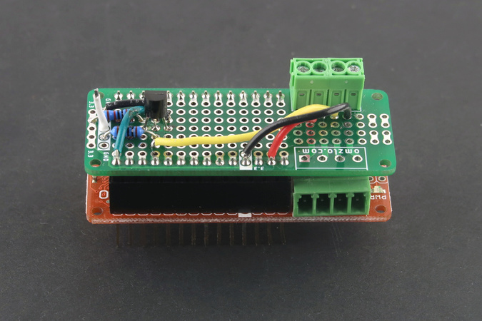
The level-shifting circuitry was constructed on an MKR prototype shield to fit nicely on a CANZERO as shown below, but any small protoboard or breadboard will likely do the trick.
Two tips that will avoid frying your CANZERO nodes:
- If you build a similar circuit, it's a good idea to test it before plugging it in a CANZERO.
- Don't insert a shield into a live/powered CANZERO. Make sure the network is powered off before installing the device.
Arduino sketch
We will create an Arduino sketch to work with our PIR sensor connected to Arduino pin 6. The sketch will create a NoCAN channel called "pir" and will output the value "Off" when the sensor is idle and the value "On" when the sensor is triggered.
During the setup phase, the sketch should:
- Connect to the NoCAN network.
- Register a NoCAN channel named "pir"
The main loop of the sketch is simple:
- Read the value of the PIR output from pin 6.
- If the PIR output value is different from the previously recorded value, send a message on the channel "pir".
Ignoring errors for now, our Arduino sketch looks like this:
#include <nocan.h>

#define PIR_PIN 6

NocanChannelId cid;
int last_r = 0;

void setup() {
  Nocan.open();
  Nocan.registerChannel("pir", &cid);
  pinMode(PIR_PIN, INPUT);
}

void loop() {
  int r;

  r = digitalRead(PIR_PIN);
  if (r!=last_r) {
    last_r = r;
    if (r==HIGH) // inverted logic
      Nocan.publishMessage(cid, "Off");
    else
      Nocan.publishMessage(cid, "On");
  }
}
The setup code above does not manage any error cases.
It is possible in some rare cases for Nocan.open() to fail.
This can happen for example if the network is powered but the nocand application quits unexpectedly.
A simple way to deal with this issue is to wait for a short delay (1 second) and try to reconnect again.
We can use the same approach to deal with a failure of Nocan.registerChannel().
Another problem with the sketch became apparent in the field. When a person passes in front of the PIR, the output of the sensor doesn't simply go from LOW to HIGH. In reality, we discovered that the output briefly goes HIGH, and then down briefly to LOW before going back to HIGH again. This is very similar to bouncing issues that you may encounter with buttons that are connected to a GPIO on an MCU. Fortunately, the solution to this problem is simple: a simple "digital" debouncing filter can be used to remove that spurious pulse in our sketch. With the error handling code and this filter, we obtain the following sketch:
#include <nocan.h>

#define PIR_PIN 6

NocanChannelId cid;

void setup() {
  for (;;)
  {
    if (Nocan.open()>0)
       break;
    delay(1000);
  }

  for (;;) {
    if (Nocan.registerChannel("pir", &cid)>=0)
    break;
    delay(1000);
  }
  pinMode(PIR_PIN, INPUT);
}

uint8_t last_state = 0;
uint8_t cur_state;

void loop() {
  int r;

  if (digitalRead(PIR_PIN) == HIGH)
    cur_state = (cur_state<<1) | 1;
  else
    cur_state = (cur_state<<1);

  if ((cur_state == 0xff || cur_state == 0x00) && (cur_state != last_state))
  {
      last_state = cur_state;
      if (cur_state==0xFF) // inverted logic
        Nocan.publishMessage(cid, "Off");
      else
        Nocan.publishMessage(cid, "On");
  }
  delay(50);
}
Testing
For testing purposes, we now assume that all the hardware is connected.
We will now log into our Raspberry Pi, where nocand should be running.
It is recommended to always run the latest version of nocand and nocanc.
You can check if you have the latest version of nocand by typing nocand version:
bash$ ./nocand version
nocand version 0.1.12-linux-arm

Checking if a new version is available for download:
 - Version 0.1.13 of nocand is available for download.
 - Download link: https://www.omzlo.com/downloads/nocand-linux-arm.tar.gz
If the command nocand version returns the message "Unknown command 'version'", you definitely need to update.
Updating the software can be done by following the installation instructions described in our tutorial.
If you have not already set up the nocand configuration file ~/.nocand/conf, you should create a minimal configuration file as follows (replace 'password' with your own secret):
$ mkdir ~/.nocand
$ echo 'auth-token = "password"' > ~/.nocand/conf
Similarly, we need to set up a matching nocanc configuration file.
Again, we first make sure we have the latest version of nocanc by running nocanc version.
For simplicity, we will assume that we are running nocanc on the same machine as the one where we have our Arduino IDE, which might be different from the Raspberry Pi where we run nocand. As indicated in our tutorial, the configuration file should contain at least the following content (replace 'password' with the matching value for nocand, and replace 'raspberrypi' with the name of the machine running nocand):
event-server = "raspberrypi:4242"
auth-token = "password"
We are now ready to launch nocand on the Raspberry Pi. If we go to the directory were we downloaded and stored the nocand executable, we type ./nocand server --log-terminal=color.
The screen will show a lot of debugging messages. Two elements are worth watching. First, lines that look like this:
2019/01/09 18:06:40 DEBUG+ Driver voltage=12.0, current sense=11 (~ 17 mA), reference voltage=3.34, status(40)=+powered.
If the indicated "Driver voltage" is 0V or far from the expected value, the network is not correctly supplied with power.
Second, early on, we should see an indication that a node has connected, which looks like this:
2019/01/09 18:04:53 INFO Device 39:26:05:43:4d:54:03:1f has been registered as node N2
On the machine running nocanc and the Arduino IDE, we can now do a few tests.
First, we can list the nodes in our NoCAN network with the command nocanc list-nodes, which should output a text similar to the following:
#2 39:26:05:43:4d:54:03:1f connected
In this example, we have one CANZERO node, numbered #2, with serial number 39:26:05:43:4d:54:03:1f that is connected to the network.
We will transform the Arduino sketch previously described into a compiled binary, using the Export compiled binary munu item in the Arduino IDE (see the instructions provided in our tutorial), and we will upload it to the CANZERO node we identified above (node #2 in our example).
./nocanc upload ~/Documents/Arduino/nocan_pir/nocan_pir.ino.omzlo_canzero.hex 2
Progress: 100%, 6004 bytes, 9606 bps.
Done
Note: The above example is from a Mac, and will look different on a Linux or Windows machine.
The command nocanc list-channels should now show the newly created 'pir' channel from our sketch:
$ ./nocanc list-channels
UPDATED #0  pir "Off"
To get the current value of the channel "pir", we will use the command nocanc read-channel pir. This command returns the current value of the channel. To wait for a change on the channel, we can use nocanc read-channel --on-update pir.
To continuously monitor changes to the value of the "pir" channel, we can also use the command nocanc monitor 9. The value '9' corresponds to channel update events (see the event API documentation for the meaning of these codes).
If you know how to write shell scripts (e.g. bash scripts on Linux), you can use nocanc to create scripts that react to events in the NoCAN network.
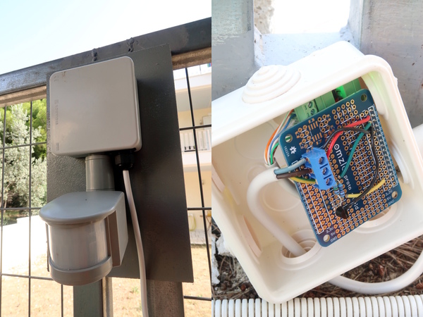
You can now fit the tested CANZERO and the PIR sensor in a box and mount it in its final location, in the house or in the garden.
Connecting the PIR to a smartphone
Blynk is a neat application that can be installed on a smartphone and interfaced with Arduino-compatible nodes, Raspberry-Pi's, ESP8266 and of course, a NoCAN network.
We have already published a tutorial describing how to connect a weather station to the blynk application. The tutorial notably showed how to display real-time temperature and humidity information in the blynk application.
We will now use the blynk platform to connect our PIR sensor to our smartphone: each time a message is published on the "pir" channel in our NoCAN network we will receive a notification on our smartphone. Note that a notification is different from the temperature and humidity data displayed in the weather station tutorial: the notification gets displayed as an alert directly on the main screen of the phone.
We will assume that you have already downloaded the blynk application for https://play.google.com/store/apps/details?id=cc.blynk or for (iPhone)[https://itunes.apple.com/us/app/blynk-control-arduino-raspberry/id808760481?ls=1&mt=8], and that you have created an account on the blynk application.
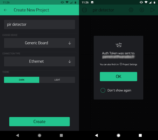
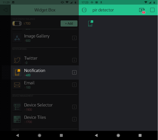
In the blynk application on the phone, we create a new project called "PIR detector". We then get an "Auth Token" sent to our email address, as shown on the two screenshots below.
Next, we tap on the little (+) icon in the project to add a notification widget as shown below.
We can then press the play icon (▷) to launch our newly created blynk project on the phone and turn our attention to the configuration of nocanc.
We first need to expand the nocanc configuration file we described previously with information related to the blynk platform, as shown in the following example.
event-server = "raspberrypi:4242"
auth-token = "password"

[blynk]
blynk-token="3f145f98f61a18477ee027cb90fc2b32"
notifiers=[ "pir" ]
As before, the values of event-server and password must be adapted to your setup. The value of blynk-token here should be changed to match the one you have received by email following the creation of the "PIR detector" blynk project. The line notifiers=[ "pir" ] simply tells nocanc to generate a blynk notification for all messages sent on the "pir" channel.
At this point, we are ready to go by simply running the nocanc blynk gateway with nocanc blynk (or nocanc.exe blynk on a windows machine). Each time the PIR sensor changes state, a notification is displayed on the smartphone.
Having multiple PIR sensors
What should you do if you have multiple PIR sensors?
The Arduino sketch we created above can run on more than one CANZERO node. All PIR sensors will then create messages on the same channel called "pir". In many application, this behavior is a feature, but here it makes sense to distinguish each PIR sensor. If we have two PIR sensors, we will probably want to know which one was triggered. One simple solution is simply to create two Arduino sketches: the first one will create a channel called "pir1" and the second one will create a channel called "pir2". There is a better approach that allows you to use the same sketch on multiple nodes. Instead of creating a channel with:
Nocan.registerChannel("pir", &cid);
You use the following expression:
Nocan.registerChannel("pir$(ID)", &cid);
In this case, the value $(ID) will be replaced by the node number.
For example, in you have the PIR sketch running on nodes 1 and 3, this will create two channels called "pir1" and "pir3".
This ID assigned to a CANZERO node will not change even if you restart nocand or reboot the raspberry pi (but be sure you have the latest version of nocand installed).
Currently the $(ID) is the only "attribute" recognized by nocand, but this feature will be expanded in the future, enabling users to define their own attributes.
Resources
The following pages provide additional information:
- The main NoCAN page, with links to documentation, APIs, schematics, etc.
- Installing a NoCAN network: step-by-step instructions for hardware and software.
- the NoCAN Arduino library description
- Buy NoCAN boards from our online store.